Making an Astrological Clock IV
This article is the fourth of a series where I build a digital clock to show real-time astronomical locations of planetary bodies.
In my first post, we wrote a script to calculate astronomical positions of the seven classical planets. In my second post, we verified the accuracy of the results of these calculations versus high-quality scientific data. In the third post we turned our astronomy measurements into astrology terms along the zodiac. See my GitHub repository that contains the code for this project.
Today we are going to set up a clock using an Arduino Nano. This will serve as our design for the astrological clock that we will make in the next post.
First thing is our shopping list. I'm not including any plastic casing or soldering while we design a prototype. I did not have any wiring or breadboards on hand, so this shopping list is inclusive of all the bits you will need. Pulling a working digital clock together for a unit cost of less than $20 is pretty neat!
| Part | Total Cost | Units | Unit Cost | Notes |
|---|---|---|---|---|
| Nano V3.0 ATmega328P Micro-Controller | $15.09 | 3 | $5.03 | LAFVIN brand. Comparable device to Arduino Nano. Comes with three USB Type-A to Mini USB cables. |
| DS3231 Real Time Clock Module | $8.29 | 3 | $2.76 | AITRIP brand. Did NOT come with batteries, Amazon listing was incorrect. |
| 3V CR2032 coin batteries | $4.99 | 4 | $1.25 | |
| OLED SH1106 OLED Display Module 1.3 inch | $17.99 | 5 | $3.60 | Hosyond brand. 128 x 64 pixels |
| Breadboard | $6.68 | 6 | $1.11 | Deyue brand |
| Jumper wire kit | $11.99 | n/a | n/a | Austor brand |
| TOTAL: | $65.03 | $15.86 | Using two breadboards, estimating $1 for jumper wires. |
The wiring for this design is very simple. You'll see a very similar design for a number of "Arduino clock" designs around. I've built a simple diagram with TinyCAD, which is free, open-source, and runs in your browser.
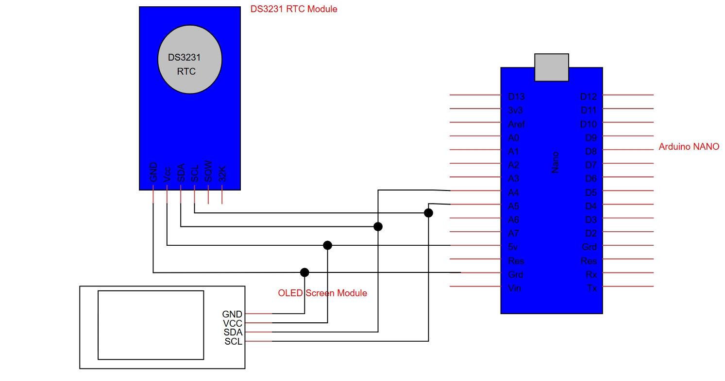
In brief, the GND pin on our RTC module and OLED display module gets hooked up to GND pin on the Arduino; we do the same for the VCC pins on each module to the 5V pin on the Arduino. Our modules communicate via the I2C Protocol, which is pins A4 & A5 on the Nano. The SDA pins on the modules go to pin A4, and the SCL pins on the modules go to pin A5.
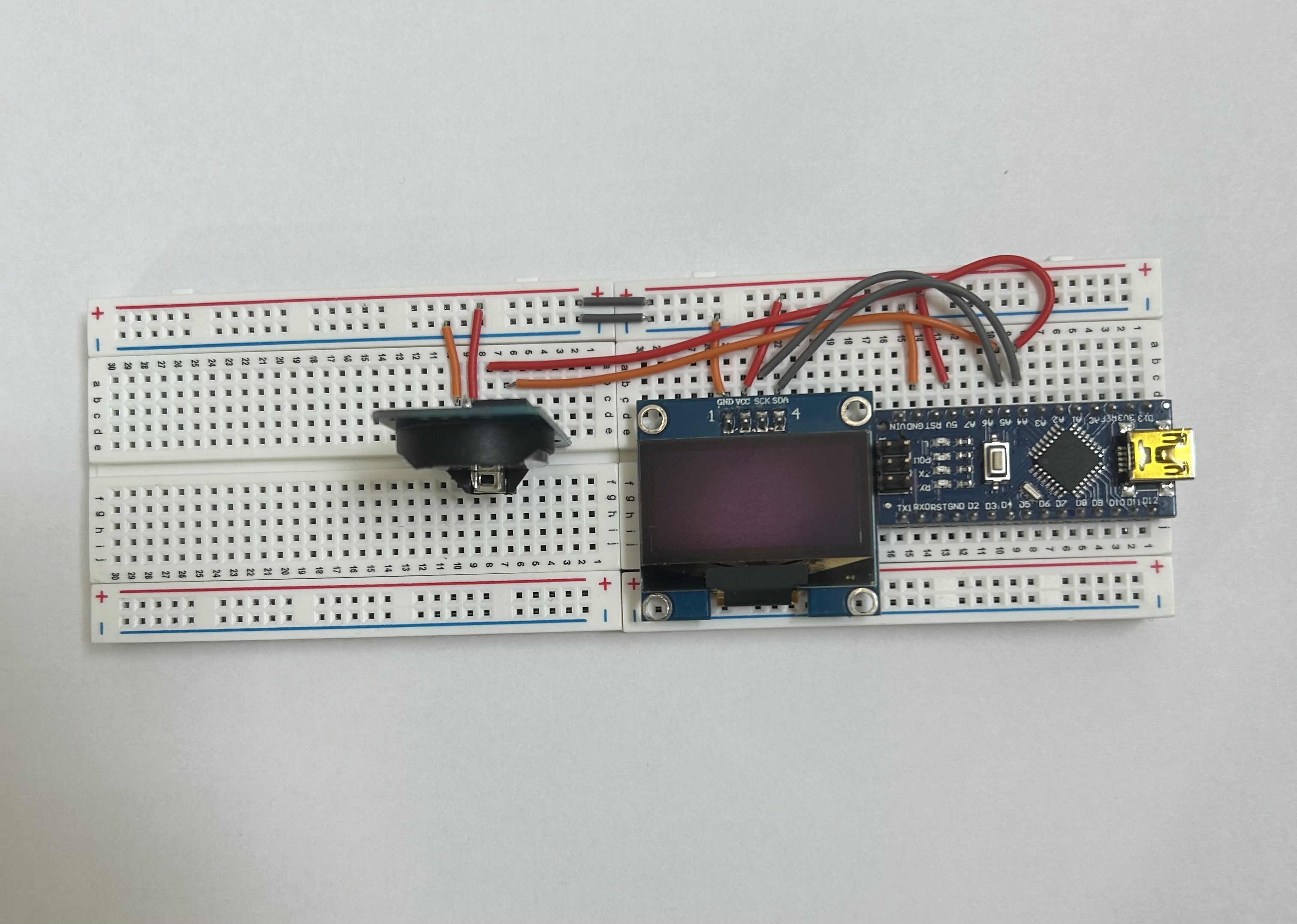
Here's what my wired prototype looks like:
Now for the software. Again, there's a number of designs for Arduino-based clocks online, but I'll attached the version I wrote below (and on the GitHub repository so you can test this design if you use it). I won't go into detail on the code, but notice that I've included a TIMEZONE_OFFSET_HOURS variable. If you want the time in UTC (as we will for our astrology calculations), you will need to offset your local time to UTC time. For instance, if you are in Washington, D.C., currently in Eastern Daylight Time = UTC-4, you would set this variable to a value of -4 if you want to display UTC.
#include <Wire.h>
#include <Adafruit_GFX.h>
#include <Adafruit_SH110X.h>
#include <RTClib.h>

#define SCREEN_WIDTH 128
#define SCREEN_HEIGHT 64
#define OLED_RESET -1

Adafruit_SH1106G display(SCREEN_WIDTH, SCREEN_HEIGHT, &Wire, OLED_RESET);
RTC_DS3231 rtc;

const int TIMEZONE_OFFSET_HOURS = 0;

const char* daysOfTheWeek[7] = {
  "SUN",
  "MON",
  "TUE",
  "WED",
  "THU",
  "FRI",
  "SAT"
};

void setup() {
  // DS3231 rtc module
  Serial.begin(9600);

  if (! rtc.begin()) {
    Serial.println("Couldn't find RTC");
    Serial.flush();
    while (1);

  }

  if (rtc.lostPower()) {
    // sets the RTC to the date & time this sketch was compiled
    // you should run this once outside the "if" block when you replace the battery
    DateTime localCompileTime = DateTime(F(__DATE__), F(__TIME__));
    uint32_t utcTimestamp = localCompileTime.unixtime() - (TIMEZONE_OFFSET_HOURS * 3600);
    rtc.adjust(DateTime(utcTimestamp));
  }

  // SH1106 oled module
  display.begin(0x3C, true);
  display.clearDisplay();
  display.setTextSize(2);
  display.setTextColor(SH110X_WHITE);
}

void loop () {
  DateTime now = rtc.now();

  display.clearDisplay();
  display.setTextSize(1);
  display.setCursor(0, 0);
  display.print(daysOfTheWeek[now.dayOfTheWeek()]);
  display.print(" ");
  display.print(now.year());
  display.print("-");
  if (now.month() < 10) display.print("0");
  display.print(now.month());
  display.print("-");
  if (now.day() < 10) display.print("0");
  display.print(now.day());
  display.print(" ");
  if (now.hour() < 10) display.print("0");
  display.print(now.hour());
  display.print(":");
  if (now.minute() < 10) display.print("0");
  display.print(now.minute());
  //display.print(":");
  //if (now.second() < 10) display.print("0");
  //display.print(now.second());

  display.display();

  // update once every 30 seconds
  delay(30*1000);
}
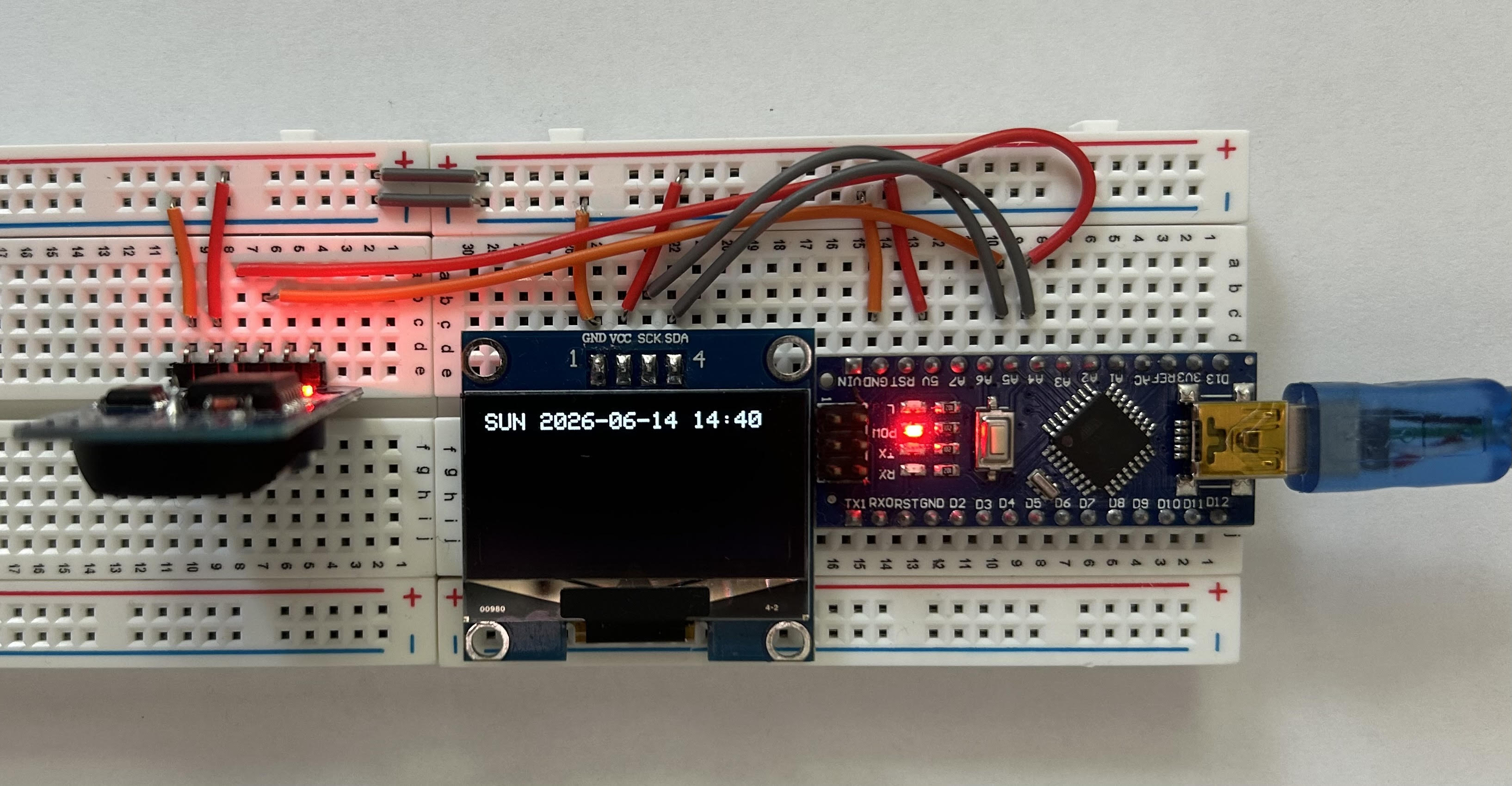
Compiling and loading this onto the Arduino gives us a succesful clock! It correctly reports the time, which was 2:40pm local time on Sunday June 14, 2026. We can unplug & replug it in as desired, and it continues ticking at the correct time. Also, instead of running connected to a computer, you can connect the USB end to a standard USB charging block operating at 5V.
In my next post, we are going to put this all together. We have the time calculated, now we just need to perform the astrology calculations on-board the Arduino and display them. I expect the biggest obstacle will be graphical design, not the calculations, but we will see!